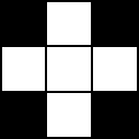
In mathematical morphology (MM)
[see TOC], the basic operators are the erosion and dilation. Through several examples, we'll see what is the
erosion and what we can do with it ...
For sake of clarity, I consider that white pixels (value of 255) are TRUE and I've configured ImageJ in such a way that the background color is black (
Process > Binary > Options check 'Black Background'
[see explanation in this post]).
1- Erosion in ImageJ
In
MM, the erosion corresponds to the minimum pixel value found in the structuring element assuming that the FALSE (value of 0) corresponds to the background and TRUE to the object(s) of interest.
In ImageJ, this operator is available in
Process > Binary > Erode and works with binary images
[see post].
 |
| Fig.1: Erosion with ImageJ. A) Original image. B) Eroded image obtained after 3 cycles. |
By default, the erosion in IJ only removes one pixel along the boundaries of the objects of interest. Thus, to remove objects (noise, defects, etc.) of diameter D, you have to repeat D/2 times the erosion operation. Fortunately, you can modify this behavior by adjusting the iterations number in
Process > Binary > Options... (Fig. 2). Thus, by clicking once on the
Process > Binary > Erode , you run
n cycles of erosion.
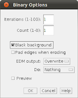 |
| Fig.2: Dialog box for tuning the binary operators |
Note: Don't forget to reset the iterations number to 1 when you've finished to work on your image.
2- Use
Erosion is often used before a particle analysis to clean up a segmented (thresholded) image or to separate touching particles.
2-1- Removing noise or unwanted particles
 |
| Fig. 3: Removing noisy particles by successive cycles of erosion. |
2-2- Separating touching objects of interest
 |
| Fig. 4: Use of erosion to separate objects of interest. A) Original image. B) Result of the Particles analysis. Only one
object (region) is counted. C) Eroded image (several cycles of
erosion were required). D) Six objects are now counted by the Particles
analysis |
3- Erosion calculated with a minimum filter
The binary ImageJ erosion operator is rather limited because you can't modify the shape of the structuring element. This limitation can be bypassed by using the minimum filter (
Process > Filters > Minimum...) and its associated masks (available in
Process > Filters > Show Circular Masks... ).
 |
| Fig.5: The 'cross' structuring element is available with a filter radius of 0.5 and the 3x3 square with a radius of 1.0. |
3-1- Erosion of binary images ...
To remove unwanted particles, this approach is more convenient than the
Process > Binary > Erode... function. Indeed, you don't need to repeat
n times the erosion process, just estimate the radius of these particles and run a minimum filter whose radius is a little bit larger than the measured defects, these particles will disappear.
3-2- ... and of gray-level images
The other main advantage to replace the erosion by a minimum filter is the
ability of working with gray-level images. In this case, the erosion
allows to remove the lightest image features as shown in Fig. 6.
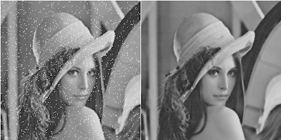 |
| Fig.6: A) Original image Lena sprinkled with white dots. B) Eroded image using a 'cross' structuring element (radius = 0.5 in minimum filter). |
4- Erosion with other shapes of structuring elements.
Erosion is really useful when it is combined with a specific shape of structuring element.
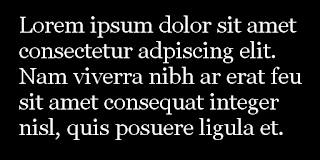 |
| Fig. 7:Text sample |
Imagine that we want to get the locations of all the characters of Fig. 7 having a vertical segment like L, t , d, b, etc. We must design a structural element resembling the vertical shape of the character to detect. Thus, a 1x20 vertical structuring element was used to compute the erosion of Fig. 8.
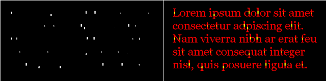 |
| Fig. 8: Erosion with a 1x20 structuring element. A) Result of erosion. B) Superimposition of the original image(Fig. 7) and the erosion (A). |
Another example with a gray-level image... composed of a horizontal blurred gray-level area. In this case, we plan to remove the vertical lines and design a horizontal structuring element.
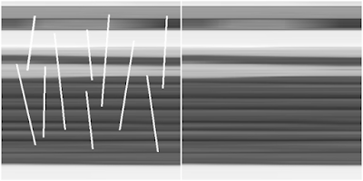 |
| Fig. 9: A) Original image. B) Eroded image calculated with a horizontal 1x20 structural element. By subtraction, you can get the vertical lines. |
Note: In ImageJ, there is no way to define your own structuring element (mask or kernel) in an erosion or minimum filter. For this example, I develop a small macro/script to run these examples.
5- Conclusion
Erosion is one of the two basic operators of MM. Now, it is time to see its counterpart: the dilation.
6- References
Character location (Figs 7 & 8 in section 4) is inspired by this Matlab
example.


thanks for this usefull article, waiting for this article like this again.
ReplyDeletebinarymate rating